19 September, 2015

Arduino: LED Matrix state as array of bytes

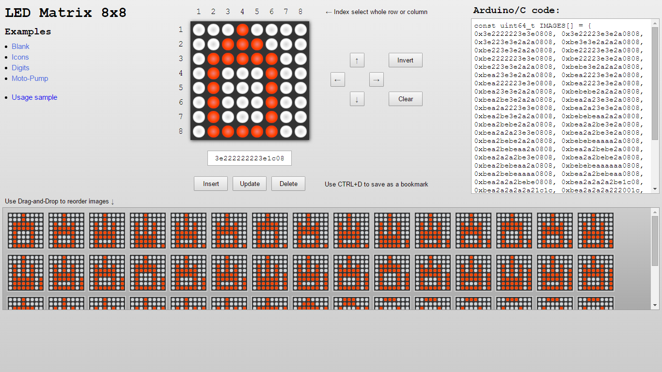
Recently I released and have written about Arduino: LED Matrix Editor

This is online editor for LED dot matrices, that helps people to make animations and save them as C-code for Arduino. In that version was only option to save matrices as unsigned 64-bit integers (uint64_t). I prefer this form as the most compact representation of the 8x8 matrix.

However some people experiencing problems with uint64_t data type (due to limitation in their software or hardware). In order to support this case (and make them happy) I just added a new option to save images as arrays of bytes in binary form:
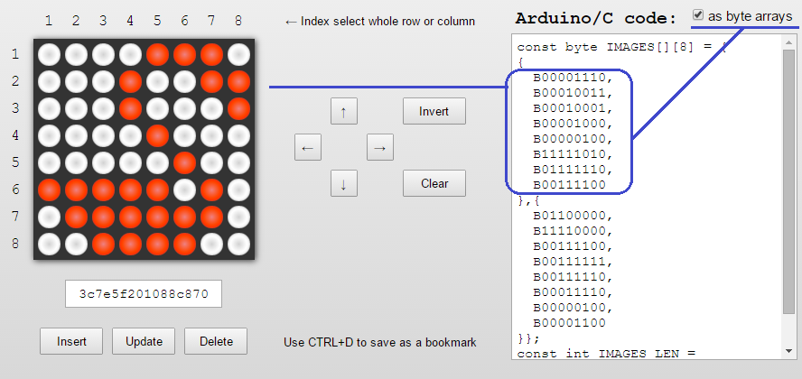
LED Matrix as byte array

Generated arrays take much more lines of code. But, nevertheless, they are more evident.

Here is a sample how to animate matrix using this code:

#include <LedControl.h>

const int DIN_PIN = 7;
const int CS_PIN = 6;
const int CLK_PIN = 5;

const byte IMAGES[][8] = {
  {
    B00010000,
    B00110000,
    B00010000,
    B00010000,
    B00010000,
    B00010000,
    B00010000,
    B00111000
  }, {
    B00111000,
    B01000100,
    B00000100,
    B00000100,
    B00001000,
    B00010000,
    B00100000,
    B01111100
  }, {
    B00111000,
    B01000100,
    B00000100,
    B00011000,
    B00000100,
    B00000100,
    B01000100,
    B00111000
  }, {
    B00000100,
    B00001100,
    B00010100,
    B00100100,
    B01000100,
    B01111100,
    B00000100,
    B00000100
  }, {
    B01111100,
    B01000000,
    B01000000,
    B01111000,
    B00000100,
    B00000100,
    B01000100,
    B00111000
  }, {
    B00111000,
    B01000100,
    B01000000,
    B01111000,
    B01000100,
    B01000100,
    B01000100,
    B00111000
  }, {
    B01111100,
    B00000100,
    B00000100,
    B00001000,
    B00010000,
    B00100000,
    B00100000,
    B00100000
  }, {
    B00111000,
    B01000100,
    B01000100,
    B00111000,
    B01000100,
    B01000100,
    B01000100,
    B00111000
  }, {
    B00111000,
    B01000100,
    B01000100,
    B01000100,
    B00111100,
    B00000100,
    B01000100,
    B00111000
  }, {
    B00111000,
    B01000100,
    B01000100,
    B01000100,
    B01000100,
    B01000100,
    B01000100,
    B00111000
  }
};

const int IMAGES_LEN = sizeof(IMAGES) / 8;

LedControl display = LedControl(DIN_PIN, CLK_PIN, CS_PIN);

void setup() {
  display.clearDisplay(0);
  display.shutdown(0, false);
  display.setIntensity(0, 5);
}

void displayImage(const byte* image) {
  for (int i = 0; i < 8; i++) {
    for (int j = 0; j < 8; j++) {
      display.setLed(0, i, j, bitRead(image[i], 7 - j));
    }
  }
}

int i = 0;

void loop() {
  displayImage(IMAGES[i]);
  if (++i >= IMAGES_LEN ) {
    i = 0;
  }
  delay(333);
}

Animation video:

12 September, 2015

Arduino: LED Matrix Editor

I would like to introduce my new mini-project LED Matrix Editor created for the Arduino community.

This is online tool for editing and creating animations for LED dot matrices.

LED Matrix Editor screenshot

It looks very simple, but it has some handy features:

  • Toggle LEDs using a mouse
  • Toggle a whole row or column by clicking the appropriate matrix's index
  • Shift the matrix Up, Down, Left or Right via the single click
  • Invert or Clear matrix
  • Collect matrices in the bottom pane and then reorder them using the Drag-and-Drop
  • Update images as well as insert new or delete existing
  • Save images as a C code for Arduino
  • Use browsing history and save images as a link or bookmark, so you never lost your creations

I hope you will be fun and happy using it.

Assume you have a matrix (based on a board with MAX7219) like this:

*This chip it is really cool and there is a good LedControl library for Arduino for this chip.

Then you have created an animation using the online editor, copied and pasted generated code to the Arduino IDE:

#include <LedControl.h>

const int DIN_PIN = 7;
const int CS_PIN = 6;
const int CLK_PIN = 5;

const uint64_t IMAGES[] = {
  0x3e2222223e3e0808, 0x3e22223e3e2a0808, 0x3e223e3e2a2a0808, 0xbe3e3e2a2a2a0808,
  0xbe223e3e2a2a0808, 0xbe22223e3e2a0808, 0xbe2222223e3e0808, 0xbe22223e3e2a0808,
  0xbe223e3e2a2a0808, 0xbebe3e2a2a2a0808, 0xbea23e3e2a2a0808, 0xbea2223e3e2a0808,
  0xbea222223e3e0808, 0xbea2223e3e2a0808, 0xbea23e3e2a2a0808, 0xbebebe2a2a2a0808,
  0xbea2be3e2a2a0808, 0xbea2a23e3e2a0808, 0xbea2a2223e3e0808, 0xbea2a23e3e2a0808,
  0xbea2be3e2a2a0808, 0xbebebeaa2a2a0808, 0xbea2bebe2a2a0808, 0xbea2a2be3e2a0808,
  0xbea2a2a23e3e0808, 0xbea2a2be3e2a0808, 0xbea2bebe2a2a0808, 0xbebebeaaaa2a0808,
  0xbea2bebeaa2a0808, 0xbea2a2bebe2a0808, 0xbea2a2a2be3e0808, 0xbea2a2bebe2a0808,
  0xbea2bebeaa2a0808, 0xbebebeaaaaaa0808, 0xbea2bebeaaaa0808, 0xbea2a2bebeaa0808,
  0xbea2a2a2bebe0808, 0xbea2a2a2a2be1c08, 0xbea2a2a2a2a21c1c, 0xbea2a2a2a222001c,
  0xbea2a2a22222001c, 0xbea2a2222222001c, 0xbea222222222001c, 0xbe2222222222001c,
  0x3e2222222222001c, 0x3e2222222222001c, 0x3e22222222221c1c, 0x3e222222223e1c08
};
const int IMAGES_LEN = sizeof(IMAGES) / sizeof(uint64_t);

LedControl display = LedControl(DIN_PIN, CLK_PIN, CS_PIN);


void setup() {
  display.clearDisplay(0);
  display.shutdown(0, false);
  display.setIntensity(0, 10);
}

void displayImage(uint64_t image) {
  for (int i = 0; i < 8; i++) {
    byte row = (image >> i * 8) & 0xFF;
    for (int j = 0; j < 8; j++) {
      display.setLed(0, i, j, bitRead(row, j));
    }
  }
}

int i = 0;

void loop() {
  displayImage(IMAGES[i]);
  if (++i >= IMAGES_LEN ) {
    i = 0;
  }
  delay(100);
}

Compile, upload and enjoy:

30 August, 2015

Arduino: manage 8-channel relay module via infrared remote control

Arduino allows us to do simple things in a simple way.

Pretty obvious desire - to control home electronics using the remote control: manage lighting, doors remotely by pressing the buttons. It is really easy. You just need these components:

Connect all together:

Arduino, 8-channel relay, IR remote control

Upload the source code to the Arduino board:

#include <IRremote.h>

const int IR_PIN = 2;

const int RELAY_PINS[8] = {12, 11, 10, 9, 8, 7, 6, 5};
int RELAY_STATES[8] = {LOW};

IRrecv irrecv(IR_PIN);

decode_results results;

void setup() {
  irrecv.enableIRIn();

  for (int i = 0; i < 8; i++) {
    pinMode(RELAY_PINS[i], OUTPUT);
  }
}

/**
 * Decode IR code to numeric button 0-9
 * Return pressed button number or -1
 */
int samsungDecode(unsigned long irValue) {
  switch (irValue) {
    case 0xE0E020DF:
      return 1;
    case 0xE0E0A05F:
      return 2;
    case 0xE0E0609F:
      return 3;
    case 0xE0E010EF:
      return 4;
    case 0xE0E0906F:
      return 5;
    case 0xE0E050AF:
      return 6;
    case 0xE0E030CF:
      return 7;
    case 0xE0E0B04F:
      return 8;
    case 0xE0E0708F:
      return 9;
    case 0xE0E08877:
      return 0;
  }
  return -1;
}

/**
 * Toggle single relay or switch ON/OFF all relays
 */
void action(int button) {
  if (button > 0 && button < 9) {
    //toggle single relay
    int i = button - 1;
    if (RELAY_STATES[i] == LOW) {
      digitalWrite(RELAY_PINS[i], HIGH);
      RELAY_STATES[i] = HIGH;
    } else {
      digitalWrite(RELAY_PINS[i], LOW);
      RELAY_STATES[i] = LOW;
    }
  } else if (button == 9) {
    //switch ON all relays
    for (int i = 0; i < 8; i++) {
      digitalWrite(RELAY_PINS[i], HIGH);
      RELAY_STATES[i] = HIGH;
    }
  } else if (button == 0) {
    //switch OFF all relays
    for (int i = 0; i < 8; i++) {
      digitalWrite(RELAY_PINS[i], LOW);
      RELAY_STATES[i] = LOW;
    }
  }
}

int lastPressedButton = -1;

void loop() {
  if (irrecv.decode(&results)) {
    int button = samsungDecode(results.value);
    if (button != lastPressedButton) {
      lastPressedButton = button;
      action(button);
    }
    irrecv.resume();
  } else {
    lastPressedButton = -1;
  }
  delay(250);
}

And enjoy by pressing buttons:

Buttons 1-8 manage relays 1-8, button 9 switch on all relays, and button 0 switch all off.

The previous day I wrote the article Arduino: scan codes from a remote control. I have scanned codes for my Samsung remote control. So if you have another remote control, just scan your codes.

29 August, 2015

Arduino: scan codes from a remote control

There are different types of infrared remote controls produced by different companies: for TV, DVD and other consumer electronics. As well all of them can be reused for Arduino using an infrared sensor.

Different remote controls may have different sets of codes, so first you need to determine what code is sent by each button. It is simple. Just connect IR sensor with Arduino:

Arduino Uno + IR sensor

Run this program:

#include <IRremote.h>

const int IR_PIN = 10;

IRrecv irrecv(IR_PIN);

decode_results results;

void setup() {
  Serial.begin(9600);  
  irrecv.enableIRIn();
}

char chars[9] = {};

void loop() {
  if (irrecv.decode(&results)) {
    Serial.println(results.value, HEX);
    irrecv.resume();
  }
  delay(100);
}

*It uses IRremote library.

Open serial monitor, press some buttons on the remote control and see the output:

Serial print scanned codes

Program prints codes for pressed buttons. For example, a remote control from the Samsung SmartTV sends these codes for numeric buttons:

  • E0E020DF 1
  • E0E0A05F 2
  • E0E0609F 3
  • E0E010EF 4
  • E0E0906F 5
  • E0E050AF 6
  • E0E030CF 7
  • E0E0B04F 8
  • E0E0708F 9
  • E0E08877 0

Arduino: print sensor value on the LED display

It is pretty simple to print a value from an analog sensor on the LED display.

For example from a light sensor like here:

Output light sensor value to led display

and when the sensor is out of light:

Output light sensor value to led display (closed)

Electronic components from the scheme above:

LED display is connected with Arduino via these 5 pins:

  • DIN - data in
  • CS - chip select
  • CLK - clock pulse source
  • GND
  • 5 V

DIN, CS and CLK are connected with Arduino via digital pins 7, 6 and 5.

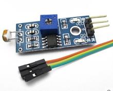
Light sensor has 3 pins:

  • GND
  • 5V
  • Signal

where signal pin is connected with Arduino via the analog pin №1.

This program reads values from the sensor 10 times per second and displays the averaged result:

#include <LedControl.h>

const int DIN_PIN = 7;
const int CS_PIN = 6;
const int CLK_PIN = 5;

const int SENSOR_PIN = 1;

LedControl display = LedControl(DIN_PIN, CLK_PIN, CS_PIN);

void setup() {
  display.clearDisplay(0);
  display.shutdown(0, false);
  display.setIntensity(0, 10);
}

void displayNumber(int number) {
  display.clearDisplay(0);
  for (int i = 0; i < 8; i++) {
    int digit = number % 10;
    number /= 10;
    display.setDigit(0, i, digit, false);
    if (number == 0) {
      break;
    }
  }
}

void loop() {
  int value = 0;
  for (int i = 0; i < 10; i++) {
    value += analogRead(SENSOR_PIN);
    delay(100);
  }
  value /= 10;

  displayNumber(value);
}